Uploads by Bpratt18
Jump to navigation
Jump to search
This special page shows all uploaded files.
| Date | Name | Thumbnail | Size | Description | Versions |
|---|---|---|---|---|---|
| 14:29, 7 May 2010 | GlassIRabs.jpg (file) |  |
221 KB | 2 | |
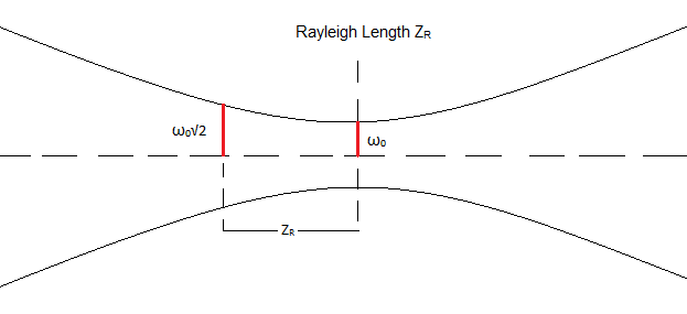
| 18:54, 23 April 2010 | Rayleigh.png (file) |  |
7 KB | 1 | |
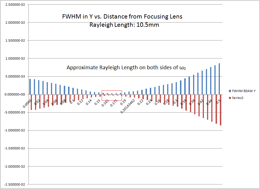
| 18:34, 23 April 2010 | Y beam.png (file) |  |
31 KB | Plotting FWHM values obtained from Y-axis projections fitted with Gaussian distributions. Note, both axis have meter units. | 1 |
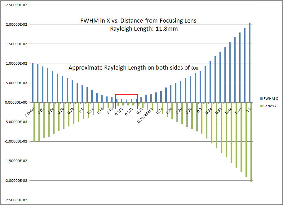
| 18:27, 23 April 2010 | X beam.png (file) |  |
33 KB | Plotting FWHM values obtained from X-axis projections fitted with Gaussian distributions. | 1 |
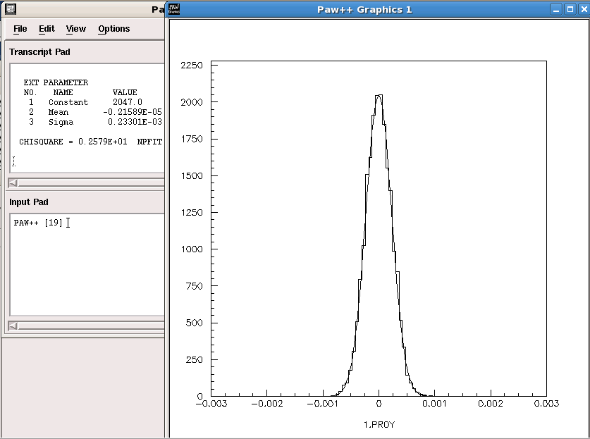
| 18:05, 23 April 2010 | G r1Y.png (file) |  |
25 KB | Y-axis Projection of Focused Beam | 1 |
| 18:04, 23 April 2010 | G r1X.png (file) |  |
27 KB | X-axis Projection of the focused beam. | 1 |
| 17:12, 23 April 2010 | R2.png (file) |  |
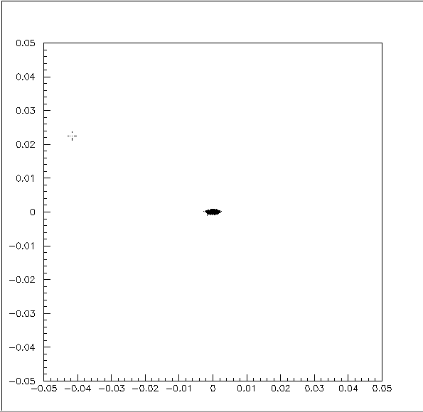
10 KB | Simulated projection of laser beam after entering a fused silica lens with the following characteristics. Lens Thickness: 6.6mm Radius of Curvature: 92mm Index of Refraction at 193nm: 1.566 | 1 |
| 14:50, 23 April 2010 | R0(2)r0(1).jpg (file) | r0(1).jpg) |
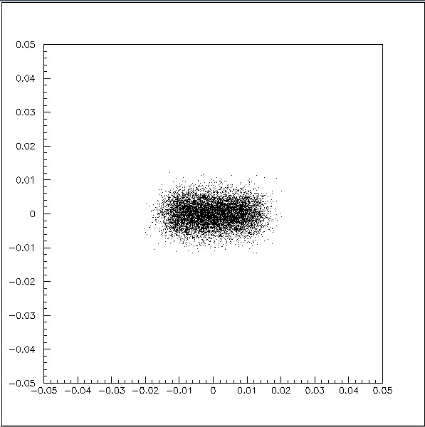
53 KB | Simulate beam profile after exiting 22x5mm aperture. | 1 |
| 13:51, 5 April 2010 | CCorderForm.pdf (file) | 99 KB | Use this form to order replacement solenoid valve for vacuum line. | 1 | |
| 13:07, 23 March 2010 | Maintenance Log-1&2.pdf (file) | 1.92 MB | 1 | ||
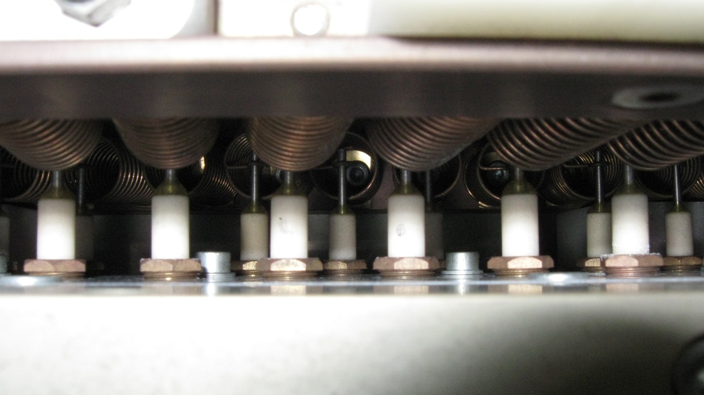
| 19:45, 5 March 2010 | Array inside.jpg (file) |  |
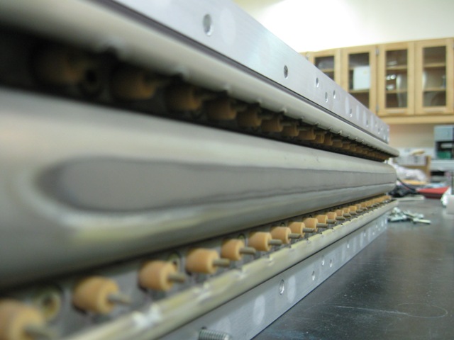
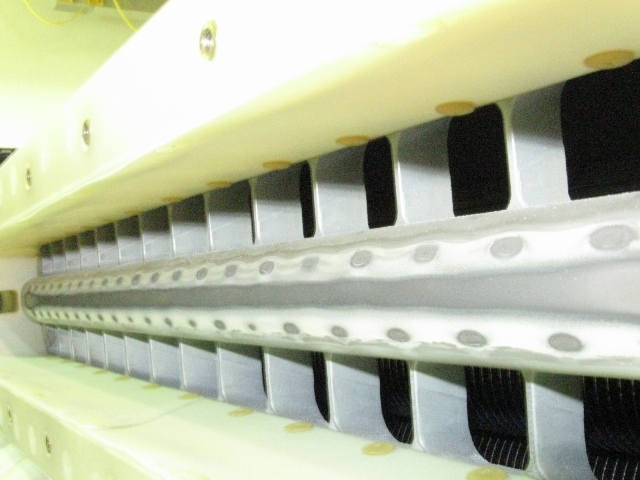
68 KB | Side angle view of spark plug enclosure. | 1 |
| 19:41, 5 March 2010 | Crust ring.jpg (file) |  |
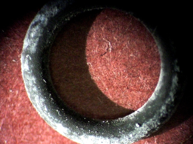
180 KB | Close up of o-ring removed from corroded spark plug. Large build up of corroded material supports the theory of observed leaking. | 1 |
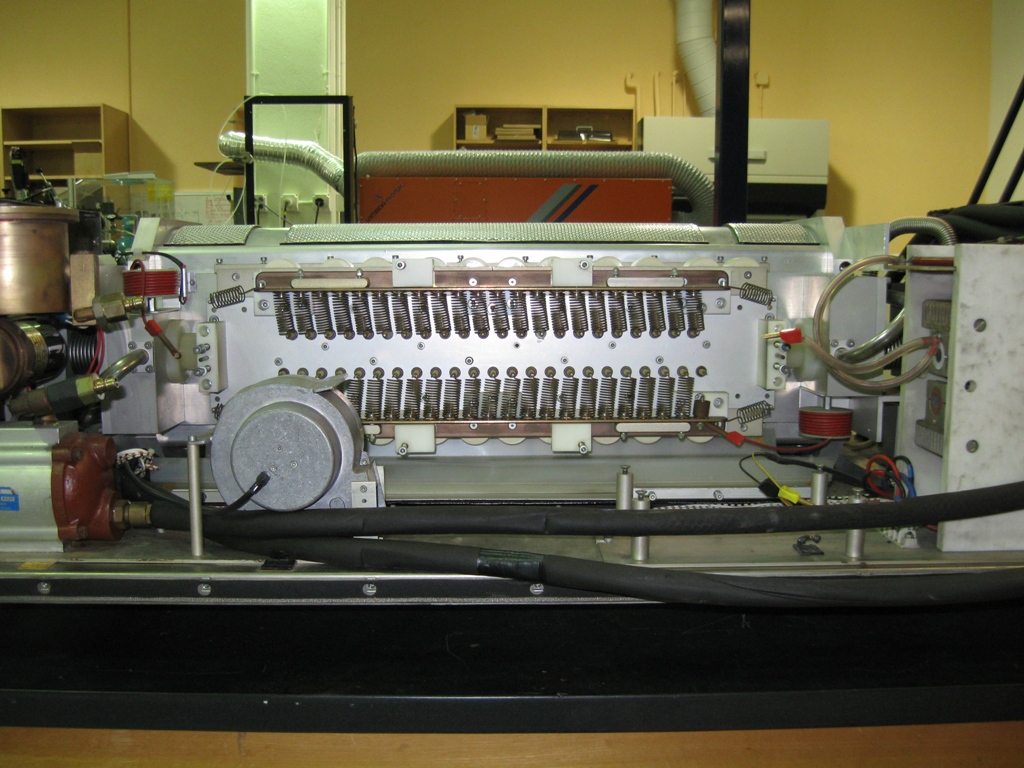
| 19:38, 5 March 2010 | Wide inside.jpg (file) |  |
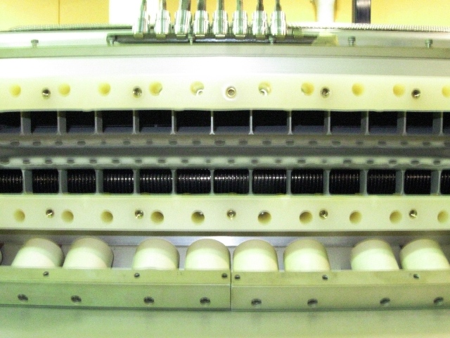
154 KB | Up front shot of the laser cavity with the spark plug array removed. | 1 |
| 19:37, 5 March 2010 | Extracted nut.jpg (file) |  |
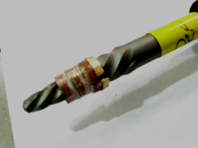
69 KB | Image showing nut right after removal. Notice the poor state of the nut's head. | 1 |
| 19:36, 5 March 2010 | Inside angle.jpg (file) |  |
129 KB | Side angled view of interior cavity. Notice the round burn patterns from the spark plug discharge. | 1 |
| 16:03, 14 February 2010 | Spark corrosion.jpg (file) |  |
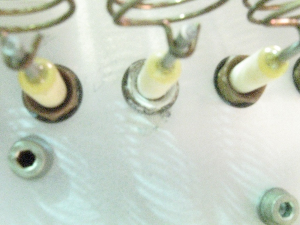
167 KB | Notice the white crust outside of the brass fitting indicating a leak source. | 1 |
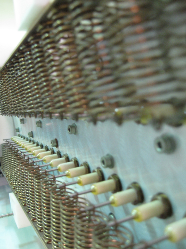
| 15:56, 14 February 2010 | Spark array.jpg (file) |  |
302 KB | Angled shot of the 45 spark plug array. These each have their own o-ring which needs replacing. | 1 |
| 15:52, 14 February 2010 | Laser removed.jpg (file) |  |
345 KB | Photo showing the removal of the thyratron, MSC, and black capacitors. | 1 |
| 23:37, 26 January 2010 | Laser gutsII.jpg (file) |  |
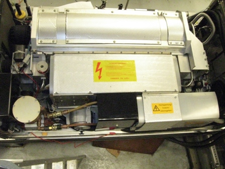
324 KB | The front of the laser is to the right. The bottom is the gas processing unit, above that are an array of white and black capacitors. | 1 |
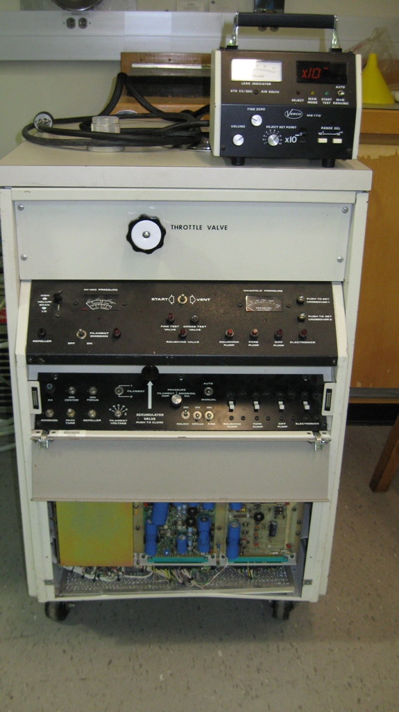
| 23:31, 26 January 2010 | Laser Hdetector.jpg (file) |  |
245 KB | This is the helium detector used by Prof. William Hines and myself to detect the leaks in the front window and spark plugs. | 1 |
| 23:30, 26 January 2010 | Laser plugs.jpg (file) |  |
193 KB | The close quarters array of spark plugs with supply the electrical discharge of the thyratron to the laser window. This is where a probable high leak source is and plans are being made to repair them. | 1 |
| 23:28, 26 January 2010 | Laser window.jpg (file) |  |
298 KB | A look at the front lens. The o-ring is actually visible behind the Mylar (orange) ring. | 1 |
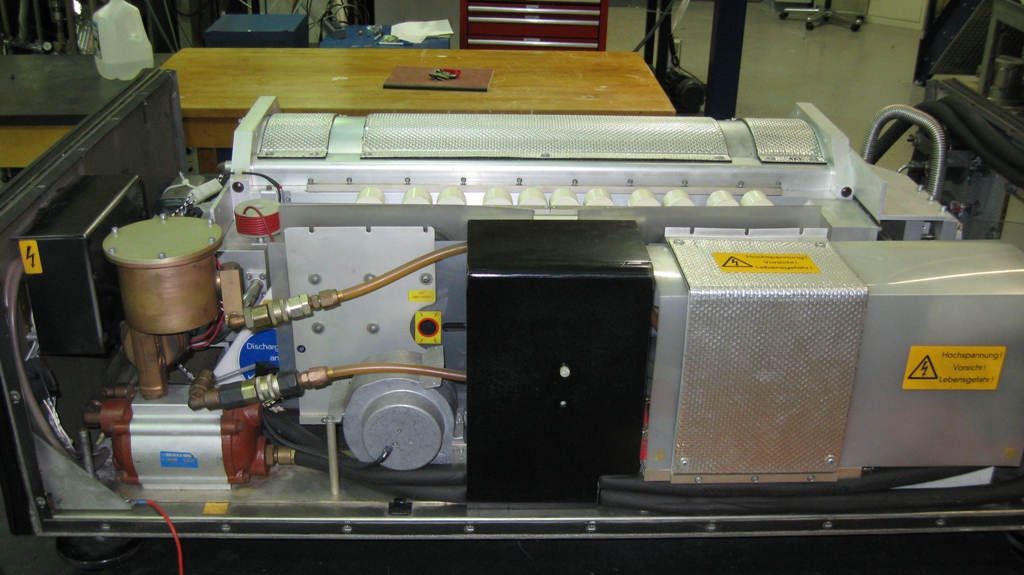
| 23:26, 26 January 2010 | Laser guts.jpg (file) |  |
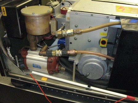
275 KB | Exposed laser head revealing the thyratron oil cooling pump and reservoir, laser window, and gas processor. | 1 |
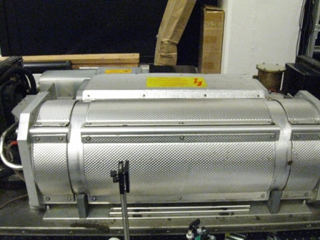
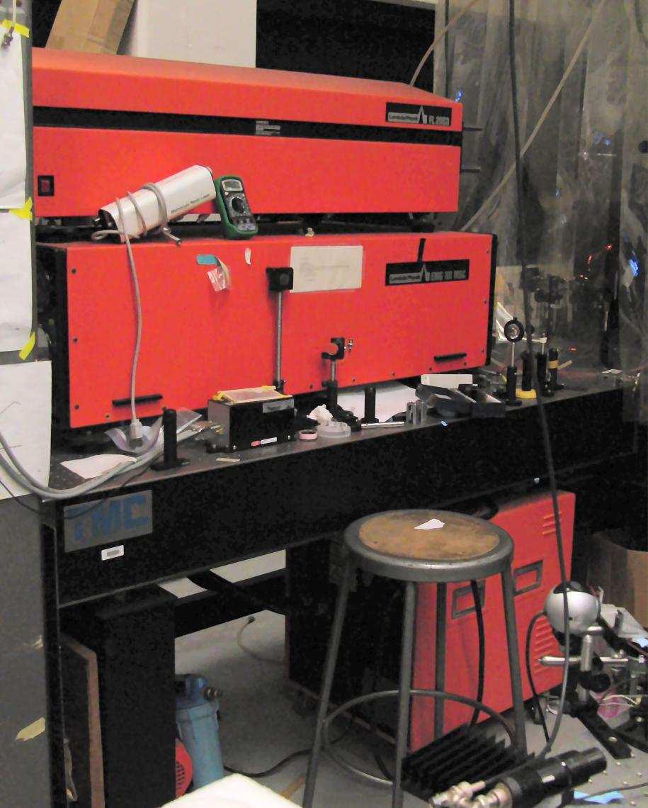
| 23:23, 26 January 2010 | Laser setup.jpg (file) |  |
221 KB | View of laser after installation is complete, notice HV power supply to the right. | 1 |
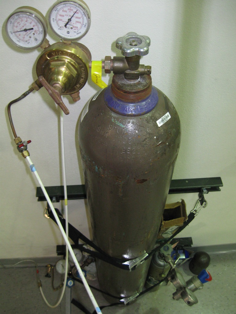
| 23:21, 26 January 2010 | Laser gas.jpg (file) |  |
201 KB | Retaining area for high pressure gas cylinders required by UConn's Environmental Health and Safety department. | 1 |
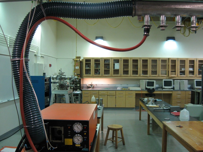
| 23:19, 26 January 2010 | Laser exhaust.jpg (file) |  |
147 KB | Completed exhaust manifold for proper ventilation of excimer system. | 1 |
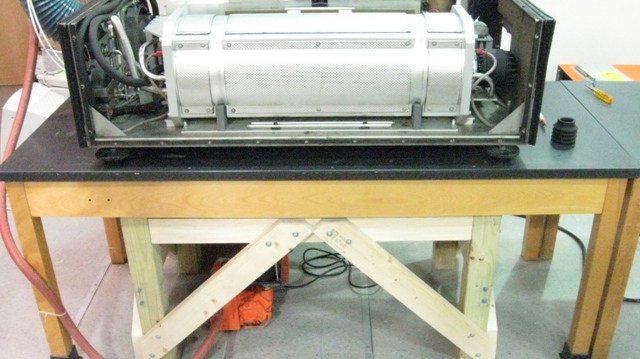
| 23:17, 26 January 2010 | Laser reinforced.jpg (file) |  |
125 KB | This photo shows the reinforced table used to support the >600lb laser. Notice the columns of support are directly under the load bearing feet of the laser. | 1 |
| 02:56, 26 January 2010 | Fused cladding.jpg (file) |  |
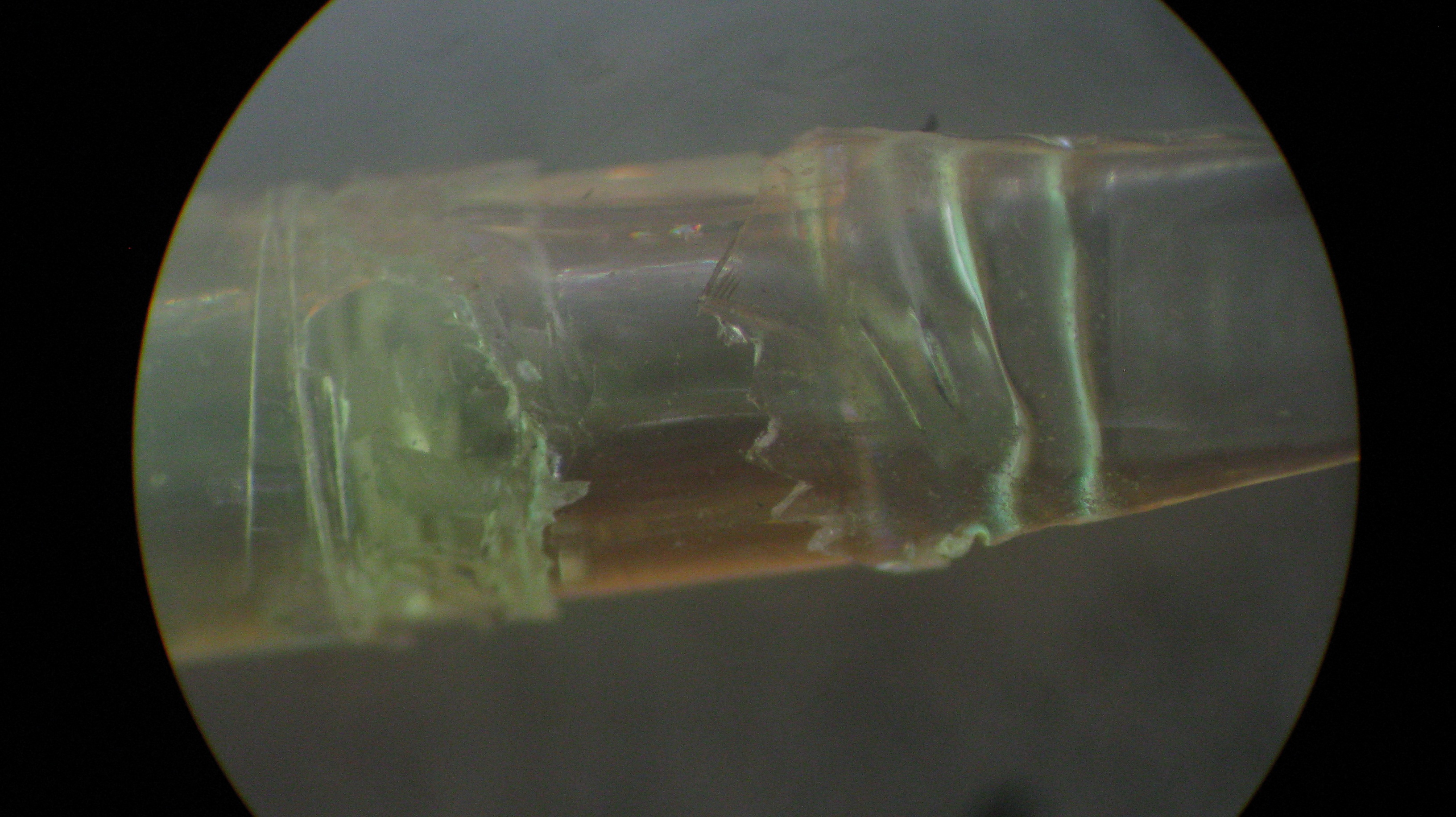
1.41 MB | This photo shows the joint of the fuse after the cladding has been stripped away. We were afraid that the weld would blend the outer cladding with the inner core negating the positive effects of an abrupt change in index of refraction. | 1 |
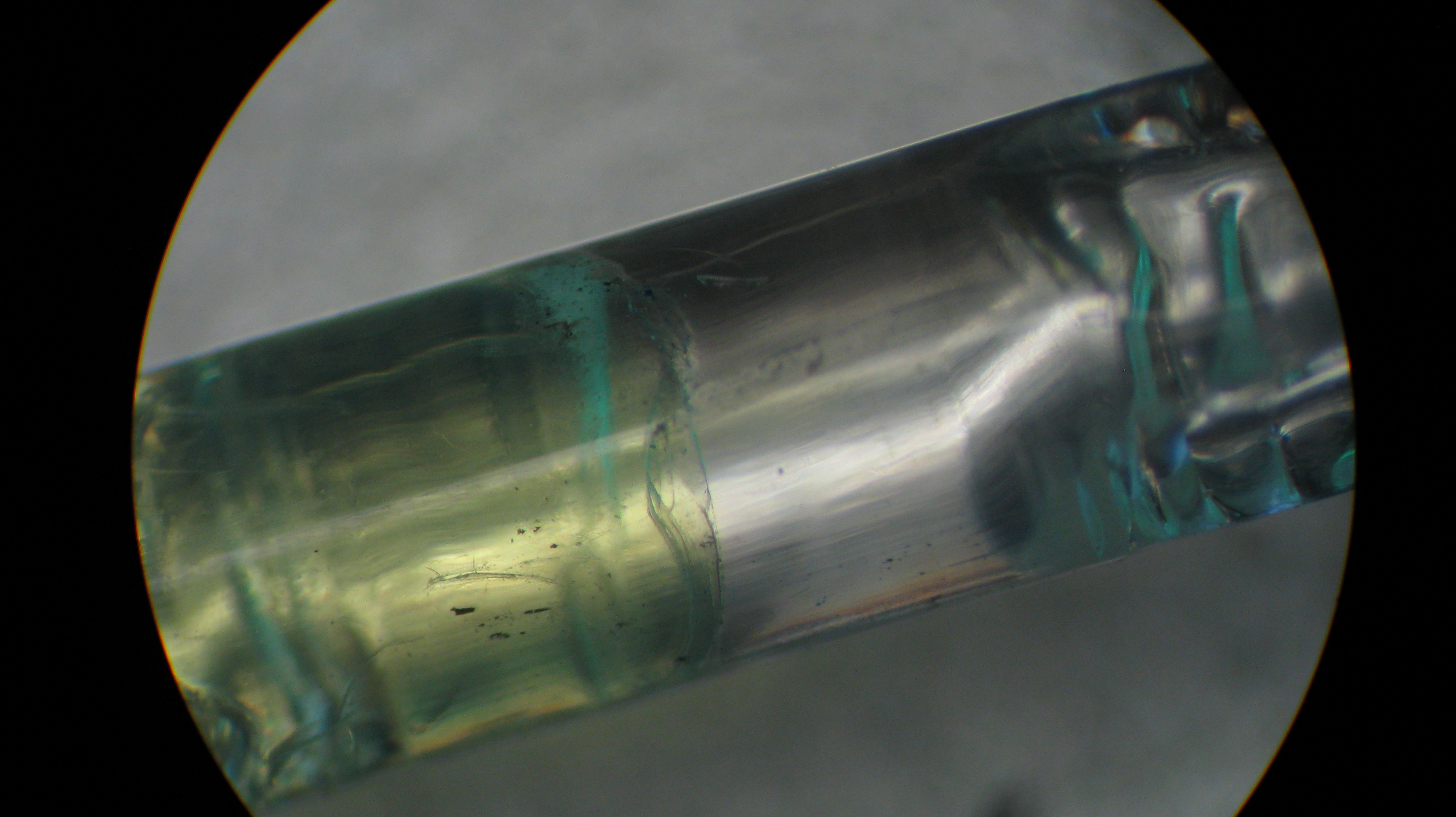
| 19:54, 25 January 2010 | Fused joint.jpg (file) |  |
1.79 MB | 1 | |
| 18:57, 22 January 2010 | Maintenance Log-1.pdf (file) | 763 KB | Maintenance Log of Excimer Laser EMG 101 MSC from November 17th, 2009 through January 22nd, 2010. | 1 | |
| 16:34, 22 January 2010 | S.O.P.pdf (file) | 156 KB | 2 | ||
| 18:18, 14 January 2010 | Silfos back.jpg (file) |  |
106 KB | Spaced 6.52mm away from the front silfos foil. Note, all of these tests were done without the collimator. | 1 |
| 18:16, 14 January 2010 | Silfos middle.jpg (file) |  |
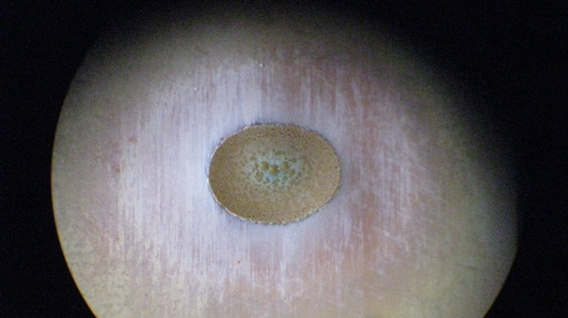
103 KB | This was centered to represent what the middle of the fibers see. Clearly, not the most intense beam spot. | 1 |
| 18:15, 14 January 2010 | Silfos front.jpg (file) |  |
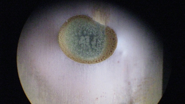
107 KB | Notice how the foil has been melted through. Meaning, of the three, this point is the closest to the focal point. | 1 |
| 18:14, 14 January 2010 | Silfos alighnment.jpg (file) |  |
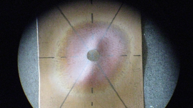
113 KB | An image showing the proper alignment of the beam spot with respect to the middle of the glass ferrule (welding spot). | 1 |
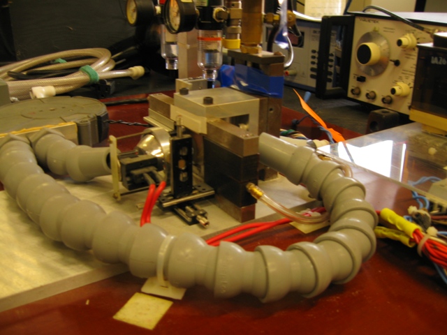
| 21:27, 14 December 2009 | Msu splicerII.jpg (file) |  |
116 KB | 1 | |
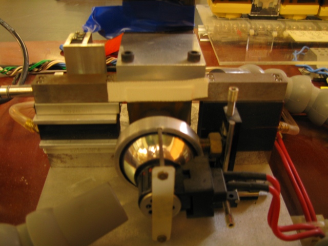
| 20:53, 14 December 2009 | Msu splicer.jpg (file) |  |
138 KB | 1 | |
| 19:34, 12 November 2009 | Excimer laser insideC.jpg (file) |  |
97 KB | 1 | |
| 19:31, 12 November 2009 | Excimer laser insideB.jpg (file) |  |
97 KB | 1 | |
| 19:27, 12 November 2009 | Excimer laser inside.jpg (file) |  |
96 KB | Inside of Lambda Physik EMG 101 MSC Excimer Laser | 1 |
| 20:18, 11 November 2009 | WaveABSRB.jpg (file) |  |
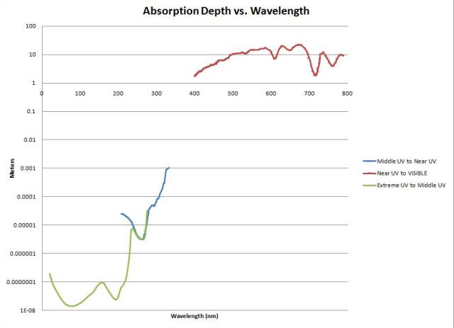
22 KB | The absorption length of given wavelength before extinction. | 1 |
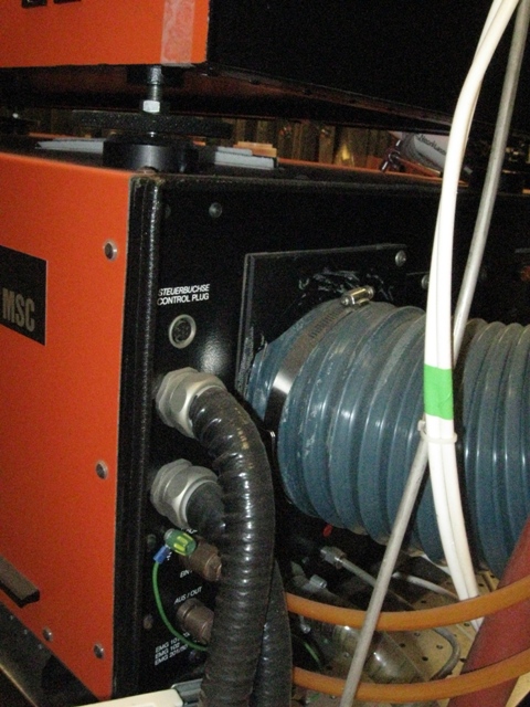
| 15:28, 5 November 2009 | BackendlaserB.jpg (file) |  |
117 KB | 1 | |
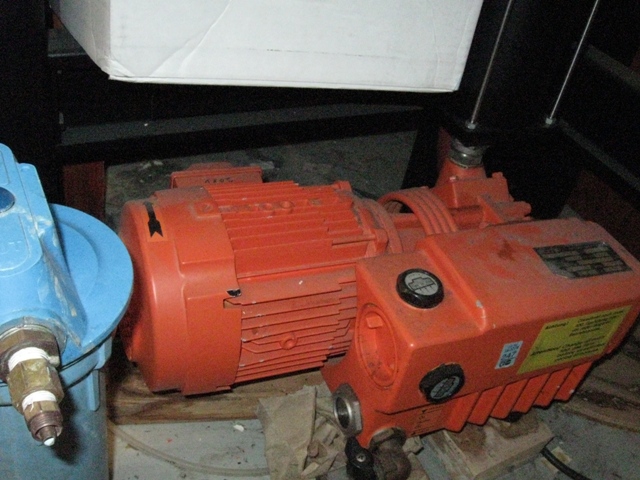
| 15:15, 5 November 2009 | Vacuum pump.jpg (file) |  |
160 KB | 1 | |
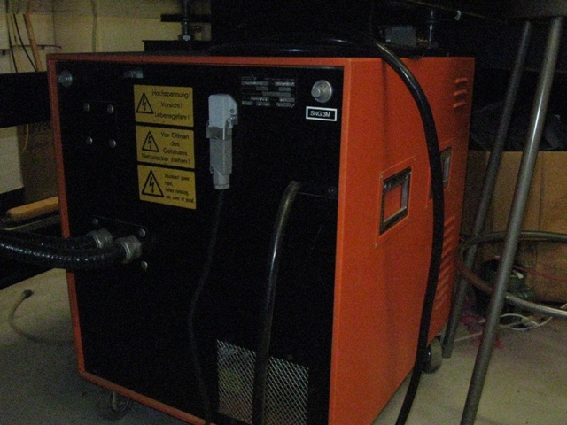
| 15:14, 5 November 2009 | Powersupply.jpg (file) |  |
158 KB | 1 | |
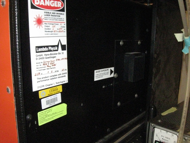
| 15:11, 5 November 2009 | Backendlaser.jpg (file) |  |
171 KB | 1 | |
| 15:07, 5 November 2009 | Laserfront.jpg (file) |  |
165 KB | 1 | |
| 18:51, 17 September 2009 | Excimer laser.jpg (file) |  |
121 KB | 1 | |
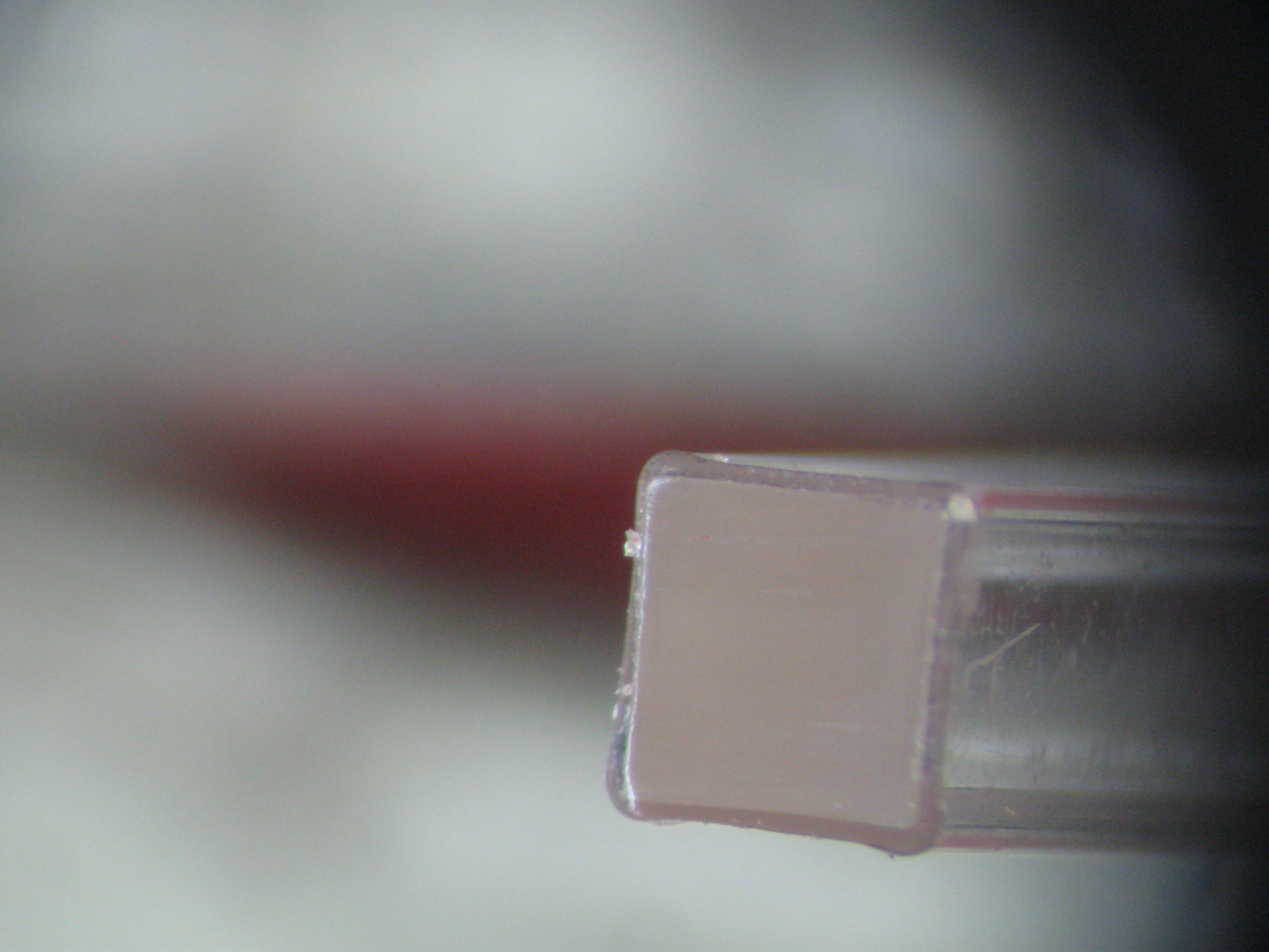
| 15:51, 8 September 2009 | IMG 0062.JPG (file) |  |
1.75 MB | Finish Polish of Waveguide Fiber | 1 |
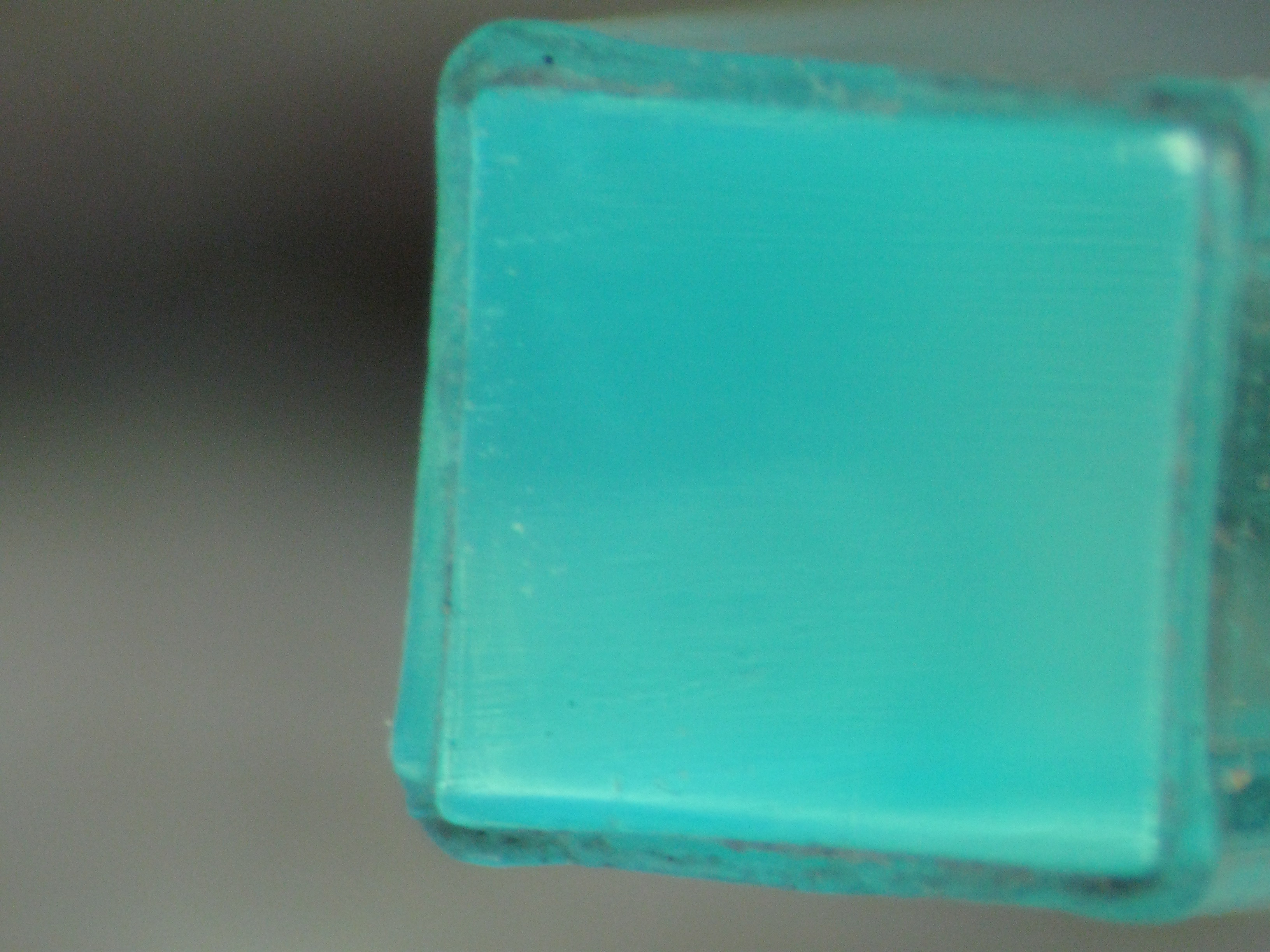
| 15:29, 8 September 2009 | Fiber 0111.jpg (file) |  |
1.64 MB | 1 | |
| 15:19, 8 September 2009 | Fiber 0111.JPG (file) |  |
1.64 MB | 1 |