Difference between revisions of "Darkbox Fiber Testing Setup"
Jump to navigation
Jump to search
(Created page with "== Purpose == The purpose of this document is to explain the procedure for setting up the UConn darkbox for fiber quality assurance testing. This entails hooking up the micros...") |
|||
| Line 38: | Line 38: | ||
*CPU (for CODA) with proper drivers | *CPU (for CODA) with proper drivers | ||
| − | == Cable Connections == | + | == Power Supply Cable Connections == |
=== 3 Channel Supply === | === 3 Channel Supply === | ||
Revision as of 19:28, 19 May 2015
Purpose
The purpose of this document is to explain the procedure for setting up the UConn darkbox for fiber quality assurance testing. This entails hooking up the microscope electronics, connecting the power supplies, and cabling the readout crate.
Equipment
Power supplies
- 1 - 60V maximum
- 1 - 3 channel (+6V/+20V/-20V)
- 2 - 18V maximum
- The 18V supplies can be substituted with batteries in series
- These are used to increase the bias voltage from 60V to 96V
Power supply cables
- Banana plug cables (number?)
- 4 - double banana plug connectors with additional banana plug openings (see pictures)
- Backplane power cord
- The end that has a rectangular, plastic block connects to the backplane. There is only one way it will fit
- The other end splits into 6 pairs of wires: the base color + the base color with a stripe. These have banana plug ends.
- LEMO cables
- 5 for the individual channel readouts
- 6 for the summed readouts
- 1 for the diode trigger
- 1 for the diode intensity feedback
TAGM components
- 1 backplane
- 1 control board
- 2 preamps
- 2 ethernet cables
- 1 for the control board
- 1 to communicate with the crate CPU
- network hub for the ethernet cables
JLab readout crate
- adc with at least 12 channels
- discriminator
- trigger
- CPU (for CODA) with proper drivers
Power Supply Cable Connections
3 Channel Supply
- There should be a wire connecting the COM (GND) and ground (GND) terminals. Make sure that the terminal is tightened down sufficiently to hold the wire in place.
- Double-plug adapters with additional connection holes have been used previously to allow for multiple connections
- Between the +6 and COM terminals.
- Between the -20V and ground terminals
- One side connected to the +20V terminal to allow for 2 connections. The other end of the double-plug was not used.
60V Supply
- Connect a double-plug adapter between the GND and (+) terminals
Connections between the 3 channel supply and the 60V supply
- There should be a banana plug cable connecting the 60V ground (GND) terminal to the three channel power supply’s COM terminal.
Connections between the 60V supply and the additional 18V supplies
- A cable should connect the 60V ground (GND) terminal to the 18V (or batteries) negative (-) terminal.
- A cable should connect the 60V negative (-) terminal with the 18V (or batteries) positive (+) terminal.
- To verify that the proper connections have been made, measure the voltage between the 60V ground terminal and the 60V positive (+) terminal. The voltages from the power supplies should have added to 96V once the 18V supplies or batteries have been added in series.
Backplane Power Cord Connections
3 Channel Supply
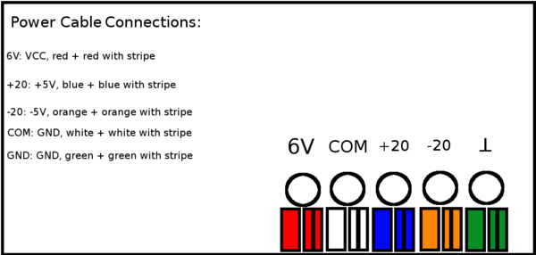
- The red and red-striped cables need to connect to the +6V (VCC) terminal of the three channel power supply.
- The orange and orange-striped cables need to connect to the -20V (-5V) terminal of the three channel power supply.
- The blue and blue-striped cables need to connect to the +20V (+5V) terminal of the three channel power supply.
- The white, white-striped, green, and green-striped cables need to connect to the ground (GND) terminals of the three channel power supply.
60V Supply
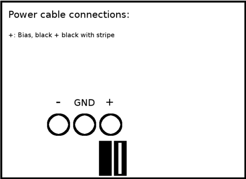
- The black and black-striped cables need to connect to the positive (BIAS) terminal of the 60V power supply.
Voltages and Currents
3 Channel Supply
- +6V: 5.84V, 0.22A
- +20V: 5.00V, 0.14A
- -20V: -5.00V, 0.00A
60V Supply
- 60V: Maxed at 60V, 0.00A
18V Supplies
- 18V: Maxed at 18V, 0.00A

